

Stopping the Burnout Cycle: Inside Envolta’s Risk Assessment Study on Electronic Card Failure at a Leading Indian Textile Plant
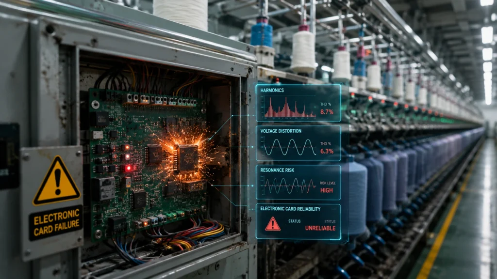
Stopping the Burnout Cycle: Inside Envolta’s Risk Assessment Study on Electronic Card Failure at a Leading Indian Textile Plant Introduction: When Replacing the Card Isn’t the Real Fix Every maintenance engineer knows the frustration of a repeat failure. A drive’s electronic card burns out, gets replaced, and within weeks — sometimes days — it fails again. The instinctive response is to blame the component, the supplier, or bad luck. But at one of India’s leading textile manufacturing facilities, Envolta Systems took a different approach: rather than treating the symptom, the team set out to diagnose the disease. This case study, delivered under the Schneider Electric EcoXpert Power Management certification, documents a comprehensive Risk Assessment Study into recurring Electronic Card failures. The investigation moved beyond the failed component itself to examine the surrounding electrical environment — harmonics, voltage distortion, resonance, and power factor behaviour — to uncover what was truly driving the failures, and to deliver a prioritised, actionable roadmap for the plant. The Objective of the Study Repeated electronic card failures in a textile plant are rarely random. They are almost always a symptom of an underlying power quality problem that stresses sensitive components every time the plant runs. Envolta’s study was scoped around five clear objectives. Identify the root cause of repeated Electronic Card failures, rather than simply replacing failed units. Assess the impact of Harmonics, Voltage Distortion, and Electrical Noise on the plant’s sensitive control electronics. Evaluate IEEE-519 compliance across the entire electrical network, benchmarking the plant against the recognised international standard for harmonic limits. Identify resonance, capacitor bank, and filter-related issues that may be amplifying — rather than suppressing — harmonic distortion. Recommend practical solutions to improve reliability and reduce downtime, grounded in field data rather than generic best practice. Key Challenges Uncovered The diagnostic phase of the study surfaced a cluster of interconnected issues — each one plausible on its own, but together painting a picture of a power quality environment under sustained stress. Frequent Electronic Card burnouts across multiple load centres, consuming disproportionate maintenance time and spares budget. High Current Harmonic Distortion (ITHD), indicating that a significant share of current flowing through the network was non-productive and electrically stressful. Parallel resonance caused by capacitor banks interacting unfavourably with system impedance — a condition that can amplify specific harmonic frequencies rather than dampen them. Voltage amplification and electrical noise propagating through the network, directly threatening sensitive control electronics. Ineffective or mistuned harmonic filters that were no longer performing their intended suppression function. Leading Power Factor and switching transients, both of which can introduce additional electrical stress during load changes. Production downtime and rising maintenance cost, the tangible business consequence of all the above. The Investigation: VFDs, PLCs, APFC Panels, and Harmonic Analysis To build an accurate picture of the plant’s electrical health, Envolta’s engineering team examined the full chain of equipment associated with the failures — VFDs and Drives, PLC and Control Systems, APFC Panels, and the Harmonic Filters and Detuned Capacitors installed to manage reactive power and harmonic content. A detailed Harmonic Analysis spanning the 3rd to 51st order was conducted across the network. This wide-spectrum analysis is significant: many assessments stop at the lower-order harmonics, but textile plants running large numbers of VFDs can generate meaningful distortion well into the higher orders, which is precisely where some of the most damaging interactions with capacitor banks and electronic components can occur. The Report Delivered The output of the study was not a single number or a verbal recommendation, but a structured, comprehensive report designed to guide both technical and commercial decision-making. Root Cause Analysis of Electronic Card failures, tracing the failures back to specific power quality conditions rather than treating them as isolated component defects. Risk Prioritization of all Load Centres, ranking which sections of the plant carried the highest probability of recurring failure. Harmonic & Power Quality Assessment, benchmarking measured distortion levels against IEEE-519 limits. A Corrective Action Plan, translating diagnostic findings into a sequenced set of interventions. Recommendations with a techno-commercial proposal, giving plant management both the engineering rationale and the investment case. Dynamic Electrical Noise Filter (ENF) Technical Specifications, for components requiring targeted noise suppression. APFC & Detuned Capacitor Bank recommendations, addressing the resonance risk identified during the audit. An Executive Summary with a priority-wise implementation roadmap, enabling leadership to sequence investment by risk and impact. The Outcome The result of this Risk Assessment Study is a comprehensive report that enables reliable operation, reduced electronic card failures, improved power quality, and enhanced plant reliability. For a textile manufacturer running continuous, multi-shift production, that combination translates directly into fewer unplanned stoppages, lower spares expenditure, and a more predictable maintenance budget. Key Highlights Comprehensive Risk Assessment Study conducted at one of India’s leading textile manufacturing facilities. Investigation covered VFDs/Drives, PLC & Control Systems, APFC Panels, and Harmonic Filters/Detuned Capacitors. Harmonic Analysis performed across the full 3rd to 51st order spectrum. Root causes identified: high ITHD, parallel resonance, voltage amplification, mistuned filters, and switching transients. Deliverables included root cause analysis, risk prioritization, IEEE-519 assessment, and a priority-wise implementation roadmap. Certified under the Schneider Electric EcoXpert Power Management programme. Outcome: reduced electronic card failures, improved power quality, and enhanced plant reliability. Expert Insights Engineering: Why Root Cause Analysis Beats Component Replacement Treating recurring electronic card failures purely as a spares and replacement problem is one of the most expensive habits in industrial maintenance. Sensitive control electronics are typically rated for a defined voltage and noise envelope; when harmonic distortion, resonance, or electrical noise repeatedly pushes the operating environment outside that envelope, replacement cards will fail again on a predictable schedule, regardless of component quality. A structured risk assessment that traces the failure back to its electrical origin — as this study does — is the only approach that breaks the cycle permanently. Design: Communicating a Complex Diagnostic in a Single Page The infographic’s three-column structure — Objective, Key Challenges, Report Delivered — mirrors a classic problem-solution-outcome narrative that is instantly legible to both engineers and
Power Factor Perfection: How a Glass Plant Hit 0.999 PF at 11kV with Static Reactive Compensation
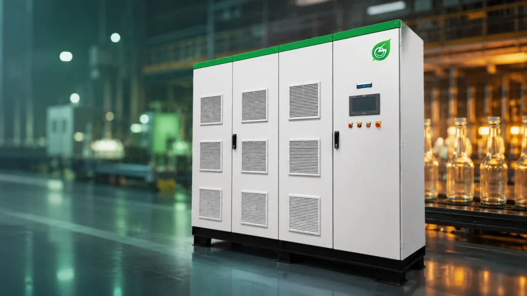
Power Factor Perfection: How a Glass Plant Hit 0.999 PF at 11kV with Static Reactive Compensation Introduction: When 0.987 Just Isn’t Good Enough In industrial power management, the difference between a power factor of 0.987 and 0.999 might look small on paper — but on a monthly electricity bill, that gap can translate into real money, real penalties, and real inefficiency. This case study, presented by Envolta Systems Pvt. Ltd. and certified under the Schneider Electric EcoXpert Power Management programme, tells the story of a glass manufacturing facility in Vadodara, Gujarat that refused to settle for “good enough.” The plant set its sights on near-unity power factor at the 11 kV high-tension (HT) side and achieved a remarkable 0.999 lagging power factor, verified over more than a week of continuous operation. The underlying story resonates far beyond the glass industry: it is about precision, reliability, and the kind of quiet, automated excellence that keeps heavy industry running smoothly. This blog unpacks the case study and explores why HT-level power factor correction is becoming a defining trend for energy-conscious manufacturers across India. The Challenge: Diagnosing the Problem The core ask was simple — improve the power factor from 0.987 to 0.999 at the 11 kV HT side — but the underlying issues were more nuanced. Glass production is an energy-intensive process involving large furnaces, motors, blowers, and compressors, many of which are inductive loads that drag power factor down. High reactive power export was dragging the plant’s overall power factor down and triggering inefficiencies. Power factor needed correction specifically at the 11 kV level, since utility incentives and penalties are calculated at the HT metering point. The existing compensation system had limited accuracy and a slow response time, unable to keep pace with fluctuating industrial loads. The client wanted a reliable, automatic, and maintenance-free solution that would not add to the plant’s operational workload. The Solution: Static Reactive Power Compensation Referenced from HT Envolta’s solution architecture is elegantly simple: power flows from the 11 kV HT side, through a transformer, down to the 415 V LT load. A Static Reactive Power Compensation (SRPC) system was installed at the LT side, but configured with a “Reference from HT Side” — ensuring that the correction applied actually moves the needle on the metric that matters to the utility. Envolta conducted a detailed power quality study to calculate the exact reactive power injection required for near-unity PF at the 11 kV HT side. The SRPC solution was installed at the LT side, configured to take its real-time reference signal from the HT side (11 kV). Result: a power factor of 0.999 achieved at the 11 kV HT side. The client independently verified an average PF of 0.999 (lagging) sustained over more than a week of continuous operation — not just a momentary peak reading. The installed panels — cream-and-grey cabinets with a touchscreen HMI are operating on-site, with overhead cable trays framing a genuinely commissioned industrial installation rather than a rendering or stock image. Key Benefits Achieved PF fine-tuned at the HT side to 0.999 lagging. Transformer losses reduced significantly. PF incentives increased under utility tariff structures. Load balanced across the distribution network. ROI achieved in less than 12 months. Client Testimony “Envolta’s team understood our requirement precisely and delivered a solution that performed at the HT side exactly as promised.” — Maintenance Head, Leading Glass Manufacturing Facility,Gujarat. Key Highlights Power factor improved from 0.987 to 0.999 at the 11 kV HT side, verified over more than a week of continuous operation. Industry: Glass Manufacturing, Vadodara, Gujarat — heavy inductive loads from furnaces, motors, and blowers. Solution: a Static Reactive Power Compensation (SRPC) system at the LT side, referencing real-time data from the 11 kV HT side. Certified under the Schneider Electric EcoXpert Power Management programme, adding third-party credibility. Five tangible benefits: fine-tuned PF, reduced transformer losses, increased PF incentives, balanced load, and ROI under 12 months. Conclusion: Small Numbers, Big Impact By pairing a hard, verified number — 0.987 to 0.999 power factor at the 11 kV HT side — with clear visuals, an honest account of the original challenge, and a real photograph of the delivered solution, Envolta Systems and its glass manufacturing client have created content that speaks equally well to engineers, plant managers, and finance teams. For any industrial facility wrestling with reactive power penalties, ageing compensation equipment, or simply looking to squeeze more efficiency out of existing infrastructure, this case study offers a clear template: diagnose precisely, install intelligently, measure at the point that matters, and verify the results over time. Facing similar power factor challenges? Contact Envolta Systems for a detailed power quality study: info@envoltasystems.com | +91 9825998879 | www.envoltasystems.com
The Hottest Threat You Cannot See: How Envolta’s Wireless Bus-Bar Temperature Monitoring System Prevents Electrical Failures Before They Strike
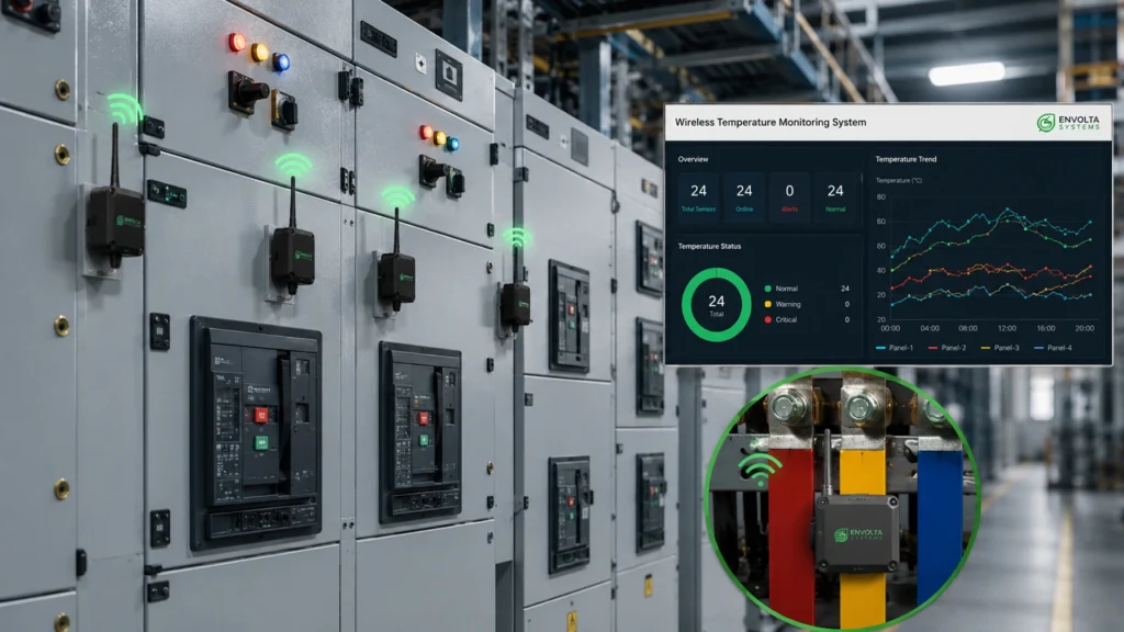
The Hottest Threat You Cannot See: How Envolta’s Wireless Bus-Bar Temperature Monitoring System Prevents Electrical Failures Before They Strike Introduction: The Danger Hiding in Plain Sight Inside every electrical panel in every industrial facility, a slow, silent process unfolds every day. Loose connections accumulate resistance. Contact surfaces oxidize. Bus-bar joints experience micro-arcing at currents too small to trip a protective relay but large enough to generate heat. Over weeks and months, this heat builds — invisible to the naked eye, undetectable without the right instrumentation — until the day a catastrophic failure makes it impossible to ignore. Overheated bus-bars, cable terminations, and breaker contacts are among the leading root causes of unplanned electrical failures in industrial plants. And because the warning signs are thermal rather than electrical, they are missed by conventional protection systems designed to respond to current, voltage, or frequency anomalies. Envolta Systems has developed a purpose-built solution for exactly this gap: the Wireless Bus-Bar Temperature Monitoring System — continuous thermal intelligence for electrical infrastructure. Where the System Is Installed: Every Critical Point in Your Electrical Network The Envolta Wireless Bus-Bar Temperature Monitoring System is designed for installation across the full range of electrical infrastructure found in industrial facilities. It is not limited to a single panel type or voltage class — it provides thermal visibility wherever heat-generating connections exist. Compatible Installation Points LT and HT Switchgear Panels — protecting both low and high voltage distribution infrastructure. PCC (Power Control Centers) and MCC (Motor Control Centers) — the nerve centers of industrial motor and power distribution. VCB (Vacuum Circuit Breaker) and ACB (Air Circuit Breaker) Contacts — components where contact resistance and thermal stress are particularly critical. Bus-Duct Systems — monitoring thermal performance across extended bus-bar runs. Power Cable Terminations — where cable-to-connector interfaces are prone to resistance buildup. Monitored Temperature Points Bus-Bar Joints — the primary hotspot in bus-bar systems, where thermal resistance concentrates. Power Cable Terminations — susceptible to oxidation and loose connection heating. ACB and VCB Jaw Contacts — high-current contact points prone to thermal degradation over time. How It Works: Wireless Sensing, Cloud Intelligence, Instant Alerts The system architecture combines wireless temperature sensors installed directly at the monitoring points with a cloud and local monitoring platform that aggregates, analyzes, and alerts based on configurable thresholds. System Highlights Wireless Temperature Sensors — eliminate the need for complex cabling within live panels, enabling installation without plant shutdown. Cloud and Local Monitoring — data is accessible both on-premise and remotely, giving operations teams and management real-time visibility from any location. Real-Time Alerts via SMS and WhatsApp — when a temperature threshold is approached or breached, alerts are delivered immediately to the responsible personnel on the channels they actually use. Up to 60 Sensors per Unit — providing comprehensive coverage of large panel arrays from a single monitoring unit. Predictive Temperature Alerts — the system identifies rising temperature trends before they reach alarm thresholds, enabling proactive intervention before a fault develops. Industries Where This System Is Already Delivering Results Envolta’s Wireless Bus-Bar Temperature Monitoring System has been implemented and is actively delivering value across a wide spectrum of manufacturing environments — demonstrating that thermal vulnerability is a universal challenge in industrial electrical infrastructure. Chemical Plants — where high electrical loads and process-critical uptime make unplanned failures particularly costly. Power Plants — where electrical infrastructure reliability is the foundation of the entire operation. Textile Plants — where production continuity depends on reliable motor and drive power. Metal and Steel Plants — where extreme electrical demands create heightened thermal risk. Pharmaceutical Industries — where cleanroom climate control and production continuity carry quality and compliance implications. Caustic Plants — where process safety and electrical reliability are inseparable priorities. Key Benefits Prevent major electrical failures by detecting thermal anomalies before they become faults. Avoid unplanned shutdowns by enabling scheduled maintenance based on actual condition data. Prevent electrical accidents by identifying dangerous overheating conditions before they lead to arc flash or fire. Reduce production losses associated with unplanned downtime caused by electrical failures. Enable predictive maintenance schedules based on real thermal trend data, replacing time-based maintenance with condition-based intervention. Reduce maintenance costs by addressing problems at the connection level rather than after equipment failure. Expert Insights: Thermal Monitoring as the Foundation of Predictive Maintenance From an industrial maintenance engineering perspective, the shift from reactive to predictive maintenance is one of the most impactful transformations available to manufacturing facilities. Traditional electrical maintenance relies on periodic visual inspection, thermal imaging cameras during planned shutdowns, and reactive response to tripping events. All three approaches share a common weakness: they require the problem to become visible or to cause a fault before action is taken. Wireless bus-bar temperature monitoring changes this paradigm fundamentally. By providing continuous, real-time thermal data from every critical connection point in the electrical infrastructure, it creates the data foundation for genuinely predictive intervention — catching a rising temperature trend at a bus-bar joint in week three, rather than responding to a bus-bar fire in week eight. The SMS and WhatsApp alert delivery is also worth noting from a practical deployment standpoint. In most industrial plants, the personnel responsible for electrical infrastructure are not sitting in front of monitoring screens. They are mobile, managing multiple systems simultaneously. Delivering alerts through channels that operators actually use — rather than requiring them to check dedicated monitoring software — dramatically increases response speed and reduces the risk of missed alerts. SEO Section: Industrial Thermal Monitoring and Predictive Maintenance Key search terms for this solution include: wireless bus bar temperature sensor, electrical panel thermal monitoring system, predictive maintenance electrical panels India, bus bar overheat detection, switchgear temperature monitoring, smart electrical panel monitoring. Semantic keywords: MCC PCC temperature alert system, wireless industrial IoT thermal sensor, electrical safety predictive maintenance, VCB ACB contact temperature monitoring, cloud-based electrical monitoring system. Conclusion: Stop the Fire Before It Starts Every year, industrial plants across India and globally experience unplanned electrical failures that could have been prevented if a temperature anomaly had been
Guarding the Grid: Envolta Systems Installs a 66kV Digital Fault Recording System at India’s Largest VFY Textile Plant in Saurashtra
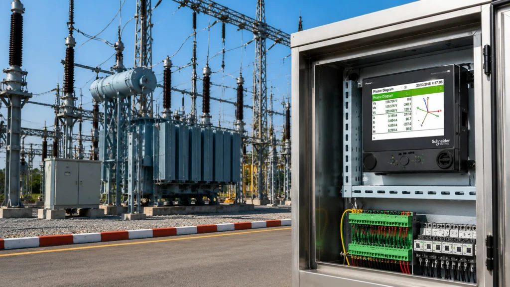
Guarding the Grid: Envolta Systems Installs a 66kV Digital Fault Recording System at India’s Largest VFY Textile Plant in Saurashtra Introduction: When the Grid Speaks, Will You Be Listening? At the scale of India’s largest Viscose Filament Yarn (VFY) textile manufacturing plant, a single undetected voltage fault can cascade into hours of production downtime, damaged process equipment, and lost product quality. For a facility receiving power at 66kV — a high-voltage supply that connects directly to the regional transmission grid — the ability to detect, record, and analyze electrical disturbances is not a convenience; it is a critical operational necessity. Envolta Systems recently completed the successful installation of a Digital Fault Recording (DFR) System at the 66kV incomer substation of this landmark plant in the Saurashtra Region of Gujarat. The project positions the facility at the forefront of power quality intelligence in India’s textile manufacturing sector. The Need: Three Gaps That Left the Plant Electrically Vulnerable Voltage Sag and Swell Monitoring At 66kV supply level, voltage sags — brief drops in supply voltage caused by faults elsewhere on the transmission network — are among the most common and most damaging power quality events for industrial facilities. A sag lasting even a few cycles can trip large motor drives, disrupt spinning and weaving processes, and result in yarn breaks that cause significant waste and quality loss. The facility needed a system capable of detecting and recording these events at high resolution. Fault Direction Detection Knowing that a fault occurred is valuable. Knowing whether the fault originated on the utility side of the supply or within the plant’s own infrastructure is essential for rapid diagnosis and appropriate response. Fault direction detection provides precisely this intelligence — enabling the plant’s electrical team to determine in seconds whether to call the utility or dispatch their own maintenance crew. Event Reporting Historical records of electrical events are invaluable for pattern analysis, insurance claims, regulatory compliance, and long-term grid interaction studies. Without a formal DFR system, these events go unrecorded and unanalyzed — leaving the plant unable to build the evidentiary history needed to negotiate with utilities or identify recurring grid weaknesses. The Solution: High-Resolution Recording with SCADA Integration Envolta Systems designed and deployed a solution that addressed all three requirements with a single integrated platform. Technical Solution Components Installed a Power Quality Analyser with in-built memory providing 256 samples per cycle — a recording resolution that captures the full waveform detail of even millisecond-duration events with high fidelity. Integrated the DFR system with Schneider Electric’s Power Monitoring Expert (PME) SCADA platform, incorporating the Power Quality Module — enabling the plant’s control room to visualize, analyze, and report on electrical events from a centralized interface. The Benefits: What the Plant Can Now Do Monitor real-time electrical data at the 66kV incomer, with live visibility of voltage, current, and power quality parameters. Access historian data for trend analysis — comparing current grid behavior with historical patterns to identify deteriorating supply quality. Automatically record Sag and Swell events whenever a fault occurs — with timestamps, waveform captures, and event duration data that provide a complete picture of every disturbance. Detect fault direction — distinguishing between utility-side and plant-side events, enabling targeted and efficient maintenance response. Generate structured event reports for management review, utility negotiations, and regulatory submissions. Key Highlights Digital Fault Recording System successfully installed at a 66kV substation — the first such system at India’s largest VFY textile plant. 256 samples per cycle recording accuracy — capturing power quality events with high-fidelity waveform precision. Integrated with Schneider Electric Power Monitoring Expert SCADA and Power Quality Module. Fault Direction Detection capability — identifying whether faults originate on the utility or plant side of the incomer. Real-time monitoring plus historian data access — enabling both immediate response and long-term trend analysis. Automatic recording of Sag/Swell events for post-event analysis and reporting. Location: Saurashtra Region, Gujarat — at India’s largest VFY textile manufacturing facility. Client Testimony “Your support and knowledge related to the system are extraordinary. Additionally, your understanding skills have made our problem easier to handle.” — Client Representative, India’s Largest VFY Textile Plant, Saurashtra Region. This testimonial speaks to something beyond technical delivery. It reflects the communication and advisory relationship that Envolta Systems built with the client’s engineering team throughout the project — a dimension of service that is often the difference between a technically completed project and a genuinely successful one. Expert Insights: DFR Systems as Competitive Infrastructure in Textile Manufacturing Digital Fault Recording at the 66kV level is a capability more commonly associated with utility substations than industrial plants. The decision to implement this technology at an industrial incomer reflects an advanced understanding of how grid interaction affects production quality and continuity in textile manufacturing. VFY production, in particular, is exquisitely sensitive to power quality events. Spinning and extrusion processes operate within tight speed and temperature tolerances, and a voltage sag lasting even 100 milliseconds can disrupt the viscose extrusion process, causing yarn defects that affect entire production lots. In a competitive market where yarn quality directly determines export viability, the ability to detect and document these events has real commercial value. From a utility relations perspective, a plant equipped with NABL-quality event recording and DFR documentation is in a fundamentally stronger position to pursue compensation or tariff remedies when grid-side faults cause production disruptions — a capability that can deliver significant financial returns over the operating life of the system. SEO Section: DFR Systems in Industrial Power Management Relevant search queries for this project include: digital fault recording system 66kV, power quality analyser substation installation, voltage sag monitoring textile industry, SCADA power quality module integration, fault direction detection industrial, Schneider PME power quality module. Semantic keywords: high resolution waveform recording, sag swell event recording industrial, grid fault analysis textile plant, power quality SCADA India, 66kV incomer monitoring. Conclusion: Intelligence at the Grid Boundary The installation of a 256-sample-per-cycle Digital Fault Recording System — integrated with Schneider Electric’s Power Monitoring Expert SCADA — at the
Harmony Restored: How Envolta Systems Achieved Power Quality Excellence with a Schneider Active Harmonic Filter at a Renowned Cable Manufacturer
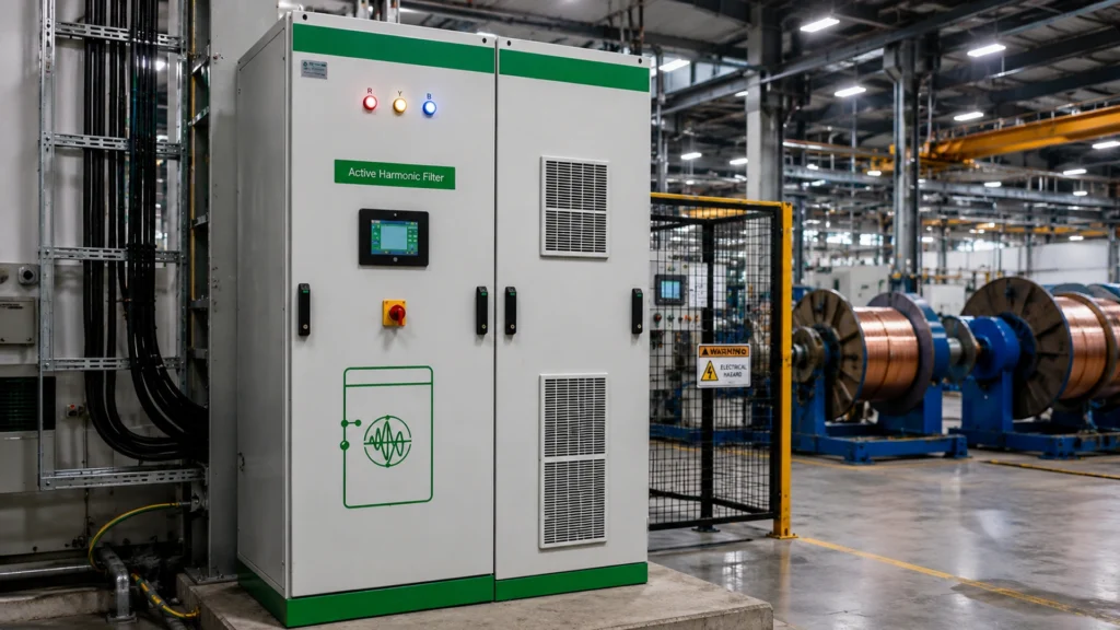
Harmony Restored: How Envolta Systems Achieved Power Quality Excellence with a Schneider Active Harmonic Filter at a Renowned Cable Manufacturer Introduction: When Harmonics Threaten Production In cable manufacturing, precision is everything. The machinery that draws wire, extrudes insulation, and winds finished product operates under tight electrical specifications — and it is acutely sensitive to the power quality of the supply feeding it. When harmonic distortion enters the picture, the consequences range from nuisance tripping of variable frequency drives to catastrophic equipment failure, unplanned downtime, and product quality degradation. For one of India’s renowned cable manufacturers, harmonic distortion had become a persistent operational challenge. Current Total Harmonic Distortion (THDi) levels reaching 20% — four times the IEEE-519 limit — were straining equipment, inflating reactive power demand, and creating an environment where reliable, high-quality production was increasingly difficult to sustain. The solution required both diagnostic sophistication and engineering precision. Envolta Systems delivered both, through the design, supply, and commissioning of a Schneider Electric Active Harmonic Filter (AHF) — completing the project in April 2026. Understanding the Problem: What 20% THDi Actually Means Total Harmonic Distortion of Current (THDi) is a measure of how distorted the electrical current waveform is relative to a pure sine wave. A THDi of 20% means that 20% of the current flowing through the facility’s electrical system consists of harmonic frequencies — predominantly the 5th, 7th, 11th, and 13th harmonics generated by Variable Frequency Drives (VFDs), rectifiers, and other non-linear loads ubiquitous in cable manufacturing. These harmonic currents do not perform useful work. Instead, they circulate through transformers, cables, and switchgear, generating additional heat and electrical stress. They cause motors to run hotter and less efficiently, increase transformer losses, interfere with sensitive electronic equipment, and can lead to premature failure of capacitors and cables. At 6.8% THDv (voltage THD), the harmonics had also penetrated the voltage waveform — a more serious condition, as voltage distortion affects every piece of equipment connected to the supply bus, not just the non-linear loads generating the problem. The Envolta Approach: From Audit to Commissioning Envolta Systems, operating as a certified EcoXpert Power Management partner of Schneider Electric, took a systematic approach to this project — one that began with rigorous diagnostic work before any equipment was specified or ordered. Project Execution Stages Harmonic Audit: A comprehensive site measurement campaign to characterize the harmonic spectrum at the affected distribution points — identifying which harmonics were dominant and which loads were generating them. Design, Manufacture, Supply, and Installation of the Schneider AHF Panel: Envolta managed the complete supply chain, from Schneider AHF specification and procurement to panel engineering, assembly, and delivery to site. Final Erection and Testing: Site installation, wiring, protection relay commissioning, and full functional testing under load conditions. Successful Commissioning: System brought to live operation with verified harmonic performance measurements confirming target compliance. The Results: Before and After, in Numbers Current THD (THDi): Reduced from 20% to 1.2% — a 94% improvement, well within the IEEE-519 limit of 5%. Voltage THD (THDv): Reduced from 6.8% to 4.5% — a significant improvement in supply voltage quality. These numbers represent more than compliance checkboxes. A reduction in THDi from 20% to 1.2% means the equipment in this facility is now operating in an electrical environment fundamentally different from before — one in which VFDs run more reliably, transformers run cooler, and production interruptions from power quality events are dramatically reduced. Key Highlights Active Harmonic Filter successfully commissioned at a renowned cable manufacturing facility. THDi reduced from 20% to 1.2% — exceeding IEEE-519 harmonic limits compliance requirements. THDv reduced from 6.8% to 4.5% — improving overall power quality at the supply bus level. Full project delivery: Harmonic Audit, Design, Manufacture, Supply, Installation, Testing, and Commissioning. Schneider Electric EcoXpert-certified solution — meeting international power quality standards. Benefits: Balanced load, harmonics per IEEE-519, improved power quality, reduced maintenance costs. Expert Insights: Active vs. Passive Harmonic Filters in Industrial Applications The choice of an Active Harmonic Filter over a passive LC filter for this application reflects a mature engineering judgement. Passive filters are tuned to specific harmonic frequencies and can actually amplify harmonics at other frequencies if the system impedance changes — a risk that is particularly significant in manufacturing environments where the load mix changes with production schedules. Active Harmonic Filters, by contrast, continuously measure the harmonic content of the load current and inject compensating currents in real time. They adapt to changing load conditions, provide broadband harmonic mitigation across the full spectrum, and do not carry the resonance risks associated with passive solutions. For a cable manufacturer with VFDs, rectifiers, and other dynamic non-linear loads, the AHF is the technically superior and more future-proof choice. Envolta’s EcoXpert Power Management certification from Schneider Electric provides assurance that the engineering team has demonstrated competency in the specification, design, and commissioning of Schneider’s power quality solutions — a credential that carries genuine technical weight in the market. SEO Section: Harmonic Mitigation in Industrial Manufacturing Key search queries for this solution type include: active harmonic filter industrial application, Schneider AHF commissioning India, harmonic mitigation cable industry, THD reduction IEEE 519, power quality improvement manufacturing, EcoXpert power management harmonic filter. Semantic keywords of relevance: VFD harmonic mitigation, power factor and THD improvement, current harmonic filter installation, harmonic audit industrial plant, power quality excellence manufacturing. Conclusion: Power Quality Is Not a Luxury — It Is the Foundation of Reliable Production For the cable manufacturer served by this project, the before-and-after contrast is as stark as the numbers suggest. A facility that was operating with 20% current harmonic distortion — an environment hostile to sensitive manufacturing equipment — now operates with THDi below 1.5%, well within international standards and conducive to reliable, high-quality production. The Schneider Active Harmonic Filter, designed, supplied, and commissioned by Envolta Systems, has delivered Power Quality Excellence — not as a marketing phrase, but as a verifiable, measured outcome. For industrial facilities where power quality problems are degrading equipment performance and threatening production reliability, this project offers a
Clear Visibility, Smarter Operations: How Envolta Systems Transformed Energy Management at a Leading Pharma Facility in Gujarat
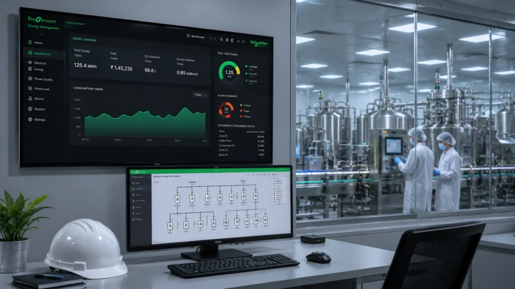
Clear Visibility, Smarter Operations: How Envolta Systems Transformed Energy Management at a Leading Pharma Facility in Gujarat Introduction: The Hidden Energy Crisis in Pharmaceutical Manufacturing Pharmaceutical manufacturing is one of the most energy-intensive industries in the world. Climate-controlled cleanrooms, continuous HVAC systems, purified water generation, and round-the-clock production lines create an unrelenting demand for electrical power — and an equally unrelenting challenge in understanding exactly where that power is being consumed and whether it is being used efficiently. For a leading pharmaceutical manufacturing facility near Vadodara, Gujarat, this challenge had become acute. Rising energy costs were compressing margins. Limited real-time visibility into power consumption made it impossible to track department-wise or equipment-wise energy usage. And without that granularity, identifying inefficiencies — let alone addressing them — was more guesswork than engineering. The solution came through a partnership between Envolta Systems and Schneider Electric — a collaboration that delivered a purpose-built Energy Management System (EMS) tailored specifically to the demands of pharmaceutical operations. The Challenge: Three Problems That Were Costing This Plant Every Day Rising Energy Costs Without granular consumption data, the facility had no objective basis for identifying where energy was being wasted. Utility bills were paid, but the underlying drivers of cost — equipment inefficiency, process optimization gaps, idle consumption — remained invisible. Limited Real-Time Visibility Energy consumption data was not available in real time. Reports were generated periodically, meaning that by the time an anomaly was identified, the operational window to correct it had already passed. In pharmaceutical manufacturing, where process deviations carry both quality and financial implications, this latency in data was a significant operational risk. Difficulty in Tracking Department and Equipment-Wise Usage With multiple production lines, utilities systems, and support functions operating simultaneously, the facility needed the ability to attribute energy consumption precisely — by department, by process, and by individual equipment. Without this capability, energy accountability was impossible to enforce and energy conservation targets were aspirational rather than measurable. The Solution: An Advanced EMS Built for Pharmaceutical Complexity Envolta Systems designed and implemented an Energy Management System that addressed each of these challenges directly, with the technical backbone of Schneider Electric’s EcoStruxure platform providing the software intelligence and connectivity infrastructure. Core System Components Delivered Real-time monitoring of both High Tension (HT) and Low Tension (LT) distribution panels across the facility. Equipment-wise and process-wise energy tracking — enabling consumption attribution at the individual machine and production line level. Automated data logging and analytics, eliminating manual data collection and the human error associated with it. On-premise customized dashboards for WAGES (Water, Air, Gas, Electricity, Steam) monitoring and temperature tracking — critical parameters for pharmaceutical compliance and process stability. Accurate billing, reporting, and compliance support — generating the documentation trail necessary for regulatory audits and internal governance. The Results: What Changed After Implementation The measurable outcomes of this EMS implementation demonstrate precisely why energy visibility is such a powerful operational lever for pharmaceutical manufacturers. Improved energy transparency across the entire plant — every department, every major load, visible in real time. Identified specific energy losses and optimization opportunities that were previously invisible in aggregate consumption data. Reduced manual intervention and reporting errors by automating the data collection and reporting cycle. Enhanced operational efficiency and decision-making quality across production, facilities, and management teams. Scalable EMS architecture designed to accommodate future expansion — additional production lines or facilities can be integrated without starting over. The Client’s Perspective “The EMS implementation by Envolta Systems has given us clear visibility of our energy consumption and helped us move towards smarter, more efficient operations.” — Client Representative, Leading Pharmaceutical Manufacturing Facility, Near Vadodara, Gujarat. This statement encapsulates the transformation that effective EMS implementation delivers: not just data, but clarity; not just monitoring, but action; not just efficiency, but confidence. Key Highlights EMS implemented at a leading pharma manufacturing facility near Vadodara, Gujarat. Solution delivered in partnership with Schneider Electric’s EcoStruxure platform. Real-time HT and LT panel monitoring with equipment-wise and process-wise tracking. WAGES dashboards delivering visibility into Water, Air, Gas, Electricity, and Steam simultaneously. Automated data logging eliminating manual reporting effort and errors. Scalable architecture supporting future plant expansion. Significant improvements in energy transparency, operational efficiency, and compliance readiness. Expert Insights: Why EMS Is Now a Pharma Industry Standard The pharmaceutical sector in India is undergoing a significant transition in its approach to energy management, driven by three converging forces: rising electricity tariffs, increasingly stringent regulatory requirements around environmental and energy reporting, and a growing recognition that energy efficiency directly affects product cost competitiveness in global export markets. ISO 50001 certification — which requires a systematic EMS — is becoming a differentiating requirement for pharmaceutical exporters seeking to serve regulated markets in Europe and North America, where institutional buyers increasingly scrutinize the sustainability credentials of their supply chains. From a technical standpoint, WAGES monitoring — the simultaneous tracking of Water, Air, Gas, Electricity, and Steam — is particularly relevant in pharmaceutical manufacturing, where these utilities are tightly regulated, directly tied to product quality, and expensive to waste. An EMS that delivers department-level WAGES visibility enables facility managers to identify precisely which process or equipment is consuming disproportionately relative to production output — a capability that typically delivers measurable savings within the first few months of operation. SEO Section: Energy Management in Pharmaceutical Manufacturing This project addresses search queries such as: EMS implementation pharmaceutical plant India, energy management system pharma manufacturing Gujarat, WAGES monitoring pharma facility, Schneider EcoStruxure pharmaceutical, real-time energy monitoring pharmaceutical industry, ISO 50001 pharma plant. Related semantic keywords: energy audit pharmaceutical, HT LT panel monitoring, automated energy reporting pharma, energy transparency manufacturing, department-wise energy tracking. Conclusion: From Energy Blindness to Operational Clarity For the pharmaceutical facility near Vadodara, the EMS implementation by Envolta Systems represents more than an upgrade to energy monitoring infrastructure. It represents a fundamental shift in how the plant is managed — from intuition-driven to data-driven, from reactive to proactive, from energy-blind to energy-aware. In a sector where margins are under pressure and operational excellence is a
Accurate Today. Reliable Always: Why On-Site Energy Meter Calibration Is the Most Overlooked Asset in Industrial Energy Management
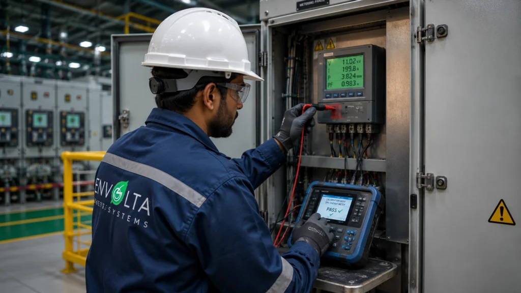
Accurate Today. Reliable Always: Why On-Site Energy Meter Calibration Is the Most Overlooked Asset in Industrial Energy Management Introduction: The Silent Inaccuracy Costing Your Plant More Than You Realize Picture this: your plant has invested in energy management software, installed smart sub-meters across every production zone, and tasked your team with tracking consumption department by department. But if the meters themselves are reading inaccurately, every decision built on that data — every procurement negotiation, every efficiency target, every compliance report — is built on a flawed foundation. Energy meter drift is not a hypothetical risk. It is a documented, measurable phenomenon that affects virtually every industrial facility over time. And yet, regular energy meter calibration remains one of the most routinely overlooked practices in plant maintenance schedules. Envolta Systems is working to change that — with professional, NABL-traceable on-site energy meter calibration services designed to bring accuracy, compliance, and confidence back to your energy data. Why Energy Meter Calibration Cannot Be Deferred Energy meters operate in demanding environments — exposed to temperature fluctuations, voltage surges, harmonic distortions, and mechanical vibration. Over time, these stresses affect measurement accuracy. A meter that once measured within ±0.5% may gradually drift to ±2% or beyond. In a plant consuming several megawatt-hours per day, that drift translates into billing discrepancies, incorrect energy intensity calculations, and skewed efficiency benchmarks. The Five Consequences of Uncalibrated Meters Billing disputes with utilities or internal departments due to systematic measurement errors. Regulatory non-compliance under ISO 50001, NABL audit requirements, and statutory energy conservation mandates. Financial overstatement or understatement of energy costs, distorting budgeting and procurement decisions. Flawed baseline data that undermines the credibility of energy conservation project ROI calculations. Sustainability reporting inaccuracies that affect ESG disclosures and carbon footprint assessments. What Makes Envolta’s On-Site Calibration Service Different The distinction between sending meters to an off-site laboratory and commissioning on-site calibration is significant — and not merely one of convenience. Laboratory calibration requires meters to be disconnected, transported, recalibrated under controlled conditions, and reinstalled. During this process, metering points go dark, energy consumption data has gaps, and production disruption is often unavoidable. Envolta’s on-site service eliminates these drawbacks. A qualified engineer arrives at the facility with advanced, NABL-traceable calibration equipment, performs the calibration in situ — typically without any requirement for plant shutdown — and issues a detailed calibration certificate for every meter tested. Service Capabilities at a Glance Voltage capability up to 600V AC — covering the full range of LT industrial metering applications. Current measurement up to 6000A using current transformers (CTs) — suitable for main incomer metering on large feeders. Frequency range of 45–65 Hz — accommodating grid frequency variations encountered in industrial environments. Parameters measured include Active Energy, Reactive Energy, Power Factor, Frequency, Voltage, and Current. Accuracy classes covered: 0.5, 1.0, and 2.0 — as per IEC 62053 and IEC 61557 international standards. Meter types supported: Single Phase, Three Phase, Multifunction, and Sub-meters — covering the full portfolio of industrial metering equipment. The NABL Traceability Advantage: What It Means for Your Plant NABL (National Accreditation Board for Testing and Calibration Laboratories) traceability is the gold standard for calibration credibility in India. A calibration certificate that is NABL-traceable means the measurement standards used during calibration can be traced through an unbroken chain of comparisons back to national and international measurement standards. For industrial facilities subject to regulatory audits — particularly those pursuing ISO 50001 Energy Management System certification, BEE (Bureau of Energy Efficiency) compliance, or stringent internal quality audits — NABL-traceable calibration documentation is not merely reassuring; it is often contractually or legally required. Key Highlights On-site calibration at the client’s facility — minimizing downtime and disruption to production. NABL-traceable calibration as per IEC/IS standards — the highest credibility standard available. Wide meter coverage: Single Phase, Three Phase, Multifunction, and Sub-meters. Comprehensive parameter testing: Power, Power Factor, Frequency, Voltage, Current, Active and Reactive Energy. Flexible scheduling — calibration performed without requiring a plant shutdown in most cases. Detailed individual calibration certificate issued for every meter, with accuracy class and test results. Supports ISO 50001, regulatory, and audit compliance requirements. Expert Insights: Calibration as an Energy Management Investment From an energy management consulting perspective, meter calibration is one of the highest-return activities available to industrial facilities — and one of the most consistently underfunded. The reason is straightforward: the cost of calibration is visible and immediate, while the cost of inaccurate meters is diffuse and accumulated over time. An energy manager who calibrates all plant meters annually and discovers that a critical feeder meter has been over-reading by 1.5% will recover the cost of calibration many times over in corrected billing alone. More importantly, they will have confidence in every energy efficiency project ROI calculation, every sustainability report, and every regulatory submission going forward. For facilities pursuing ISO 50001 certification, the standard’s Section 9.1.1 on monitoring, measurement, analysis, and evaluation explicitly requires that measurement equipment be calibrated and maintained. NABL-traceable calibration certificates are the most defensible documentation available to demonstrate compliance with this requirement. SEO Section: Key Search Queries This Service Addresses Industrial energy managers and plant engineers searching for this type of service typically use queries such as: on-site energy meter calibration service, NABL accredited meter calibration, energy meter accuracy testing plant, industrial meter calibration without shutdown, IEC 62053 energy meter calibration, sub-meter calibration certificate India. Secondary terms include: energy meter drift correction, ISO 50001 meter calibration requirement, three phase energy meter calibration service, power quality meter accuracy testing. Conclusion: Trust Your Data — After You Have Verified Your Meters Data-driven energy management is only as reliable as the instruments that collect the data. For industrial facilities that have invested in energy monitoring systems, sub-metering networks, and EMS platforms, the integrity of that investment depends directly on the accuracy of the meters feeding it. Envolta Systems’ On-Site Energy Meter Calibration Service addresses this foundational requirement with professional precision — delivering NABL-traceable results, comprehensive coverage across meter types and accuracy classes, and flexible scheduling that respects the operational
Powering a Greenfield Future: Envolta’s 180kVAr, 6.6kV MV Fixed PFC Panel Achieves Near-Unity Power Factor at a Landmark Chemical Plant

Powering a Greenfield Future: Envolta’s 180kVAr, 6.6kV MV Fixed PFC Panel Achieves Near-Unity Power Factor at a Landmark Chemical Plant Introduction: Getting Power Right from Day One There is a critical window in any greenfield industrial project — that decisive period when the electrical infrastructure is being commissioned for the first time. Decisions made during this window shape every energy bill, every compliance audit, and every unit of production efficiency for decades to come. This is why leading chemical manufacturers increasingly recognize that power factor correction is not an afterthought; it is a foundational engineering priority. Envolta Systems recently demonstrated exactly this philosophy with the successful supply and commissioning of a 180kVAr, 6.6kV Medium Voltage Fixed Power Factor Correction (PFC) Panel at a renowned chemical industry greenfield project. The result: a facility that begins its operational life with near-unity power factor, optimal energy efficiency, and full grid compliance. The Project: Technical Scope and Site Context Medium-voltage power factor correction at the 6.6kV level demands a significantly higher degree of engineering precision than standard low-voltage capacitor banks. At this voltage class, component selection, insulation coordination, and protection relay integration are all non-trivial decisions that can have serious consequences if handled incorrectly. Project Specifications at a Glance Equipment Supplied: 180kVAr, 6.6kV Medium Voltage Fixed Power Factor Correction (PFC) Panel. Commissioning Site: A greenfield chemical manufacturing facility. Installation Point: Across the Chiller system operating on a 6.6kV supply system. Power Factor Improvement: From 0.89 to 0.98 at the Chiller load level. Operating Mode: Auto Logic — the PFC panel activates automatically whenever the Chiller is online. Why a Fixed PFC Panel? Understanding the Engineering Decision Power factor correction equipment comes in two broad categories: fixed (static) and automatic (dynamic). The choice between them depends on the nature of the load being corrected. A fixed PFC panel provides a constant reactive power injection — it is ideal for loads that run consistently at a known power level, drawing a predictable reactive demand. The Chiller system at this chemical facility is precisely such a load. When a large industrial chiller is running, its reactive power demand is relatively stable and predictable. A fixed 180kVAr bank, correctly sized to compensate the chiller’s reactive demand, delivers reliable correction without the switching transients that can accompany stepped automatic systems. The Auto Logic implementation — where the PFC panel engages and disengages automatically based on chiller operating status — adds a layer of intelligent automation that ensures the correction is only applied when needed, protecting against capacitor overvoltage during light-load conditions. The Measurable Outcome: From 0.89 to 0.98 Power Factor Power factor improvement from 0.89 to 0.98 may appear to be a modest numerical shift, but its engineering and economic significance is considerable. At 0.89 power factor, a facility draws meaningfully more current from the grid than its actual productive load requires — that excess current flows through transformers, cables, and switchgear without doing useful work, generating heat and reducing the effective capacity of the entire electrical system. At 0.98 power factor, reactive current is reduced to near-negligible levels. The practical benefits cascade across the entire electrical infrastructure: reduced transformer loading, lower cable losses, improved voltage regulation at the chiller terminals, and elimination of utility power factor penalty charges that would otherwise accumulate month after month. Key Highlights Successful supply and commissioning of a 180kVAr, 6.6kV MV Fixed PFC Panel at a greenfield chemical plant. Power factor at the Chiller level improved from 0.89 to 0.98 — a significant step toward unity. Auto Logic control ensures the PFC panel operates inline with the Chiller, preventing overcorrection. Medium-voltage installation at the 6.6kV level demonstrates advanced engineering capability. Installation at a greenfield site ensures optimal electrical performance from day one of production. Outcome: Maximized energy efficiency, reduced reactive power penalties, and enhanced electrical stability. Expert Insights: Why Greenfield Projects Must Prioritize Power Quality From an electrical engineering and project management perspective, the commissioning of power factor correction equipment at greenfield chemical plants represents an investment with among the fastest payback periods in the industrial energy efficiency toolkit. Utility tariffs in India and across most industrial economies include a power factor component — facilities operating below a defined threshold (typically 0.85 or 0.90, depending on the utility) face monthly penalties, while those operating above near-unity often receive tariff incentives. At a 6.6kV supply level serving large process equipment such as chillers, compressors, and centrifugal pumps, the reactive power demand can be substantial. A correctly engineered fixed PFC panel at this voltage level typically delivers payback within 12–24 months through combined savings from penalty elimination, reduced transformer losses, and improved cable utilization. The technical sophistication of installing MV-class equipment — with appropriate protection relays, surge arrestors, and insulation coordination — is also a differentiator. Not all power factor correction contractors are equipped to work safely and competently at 6.6kV. Envolta Systems’ track record in this domain represents a meaningful value proposition for chemical and process industry clients. SEO Section: Power Factor Correction in the Chemical Industry Key search terms relevant to this project include: medium voltage power factor correction, 6.6kV capacitor bank installation, fixed PFC panel for industrial chiller, chemical plant power factor improvement, MV PFC panel greenfield project, power factor penalty reduction India. Secondary semantic keywords include: reactive power compensation 6.6kV, industrial capacitor bank commissioning, energy efficiency chemical manufacturing, power quality optimization chemical plant. Conclusion: The Right Foundation for a High-Performance Plant A greenfield chemical plant represents an enormous capital investment — and the quality of its electrical infrastructure will determine how efficiently that investment performs for its entire operational life. Envolta Systems’ commissioning of the 180kVAr, 6.6kV MV Fixed PFC Panel at this facility is a clear demonstration that power quality engineering, when done right, delivers lasting value from the very first day of production. For chemical manufacturers planning new facilities or expanding existing ones, the lesson here is straightforward: power factor correction at the medium voltage level is not an optional upgrade — it is a foundational design requirement.
From Manual to Auto: How Envolta Systems Delivered a 3.5 MVAR HT APFC Panel Retrofitting Success at a Leading Tyre Industry
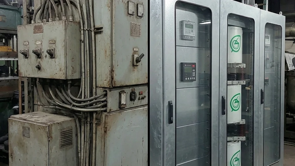
From Manual to Auto: How Envolta Systems Delivered a 3.5 MVAR HT APFC Panel Retrofitting Success at a Leading Tyre Industry Introduction: When a Fire Incident Becomes a Turning Point In industrial power management, complacency is never truly affordable — and for one of India’s renowned tyre manufacturers, a fire incident inside the air-core reactor of an existing HT APFC panel made that reality unmistakably clear. What followed was not merely a repair job. It became an opportunity for a comprehensive upgrade that would transform the facility’s entire approach to power factor correction.Envolta Systems stepped in with a complete retrofitting solution — and the results tell a story of restored power quality, enhanced operational safety, and future-ready electrical infrastructure. Understanding the Challenge: What Was at Stake The existing 3.5 MVAR High Tension Automatic Power Factor Correction (HT APFC) panel at the tyre industry client had accumulated several critical issues that could no longer be deferred. The fire incident in the air-core reactor was the most urgent trigger, but deeper engineering assessment revealed a cluster of interconnected problems. Project Challenges at the Time of Engagement A fire incident had compromised the air-core reactor within the existing HT APFC panel, necessitating immediate intervention. The fresh design requirement for both air-core reactors and capacitor banks demanded engineering from the ground up rather than a simple component swap. The panel was operating exclusively in Manual Mode, requiring manual intervention to adjust power factor — a situation incompatible with modern grid compliance expectations. A new Vacuum Circuit Breaker (VCB) needed to be retrofitted within the existing HT panel infrastructure, adding structural and electrical complexity to the project. Before retrofitting, the power factor measured below 0.85 PF — a value that typically attracts utility penalty charges and reduces the effective capacity of the electrical infrastructure. Correcting this was not merely a matter of regulatory compliance; it was a direct economic opportunity. Envolta’s Execution: A Systematic, Safety-First Approach Envolta Systems approached this project with a methodology that balanced urgency with engineering precision. Rather than recommending full panel replacement — which would have extended downtime and inflated costs — the team designed a targeted retrofitting strategy that preserved the viable elements of the existing infrastructure while comprehensively addressing every identified deficiency. Key Execution Steps Supplied and seamlessly integrated a new VCB Panel within the existing panel framework, eliminating the need for a complete structural overhaul. Designed custom LC Filters tailored to the specific harmonic profile and reactive power demand of the tyre manufacturing facility. Retrofitted new capacitors and air-core reactors within the existing HT APFC panel, replacing all components compromised by the fire incident. Enhanced operational safety by installing dedicated temperature sensors within each section of the panel — a proactive step that guards against future thermal incidents. Completed all control wiring, site execution, testing, and commissioning in-house, ensuring end-to-end accountability for project quality. The Transformation: Before vs. After The contrast between the pre-retrofitting and post-retrofitting state is striking — both visually and in terms of measurable electrical performance. The before-state photographs show aging equipment bearing the markings of a third-party manufacturer, operating in manual mode with visible signs of wear. The after-state reveals newly installed Envolta-branded capacitor banks, clean wiring, and a panel now configured for fully automatic operation. Power Factor Before: Less than 0.85 PF (Manual Mode, reactive penalty risk) Power Factor After: Greater than 0.99 PF (Auto Mode, full grid compliance) A power factor of 0.99 is effectively near-unity — the theoretical ideal for reactive power compensation. Achieving this from a starting point below 0.85 represents not only a technical victory but a tangible financial benefit, as utilities typically reward near-unity power factors with lower tariff rates and eliminate penalty surcharges. Key Highlights 5 MVAR HT APFC panel successfully retrofitted at a prominent tyre manufacturing facility. Power factor elevated from below 0.85 to above 0.99 — a near-unity improvement. Panel transitioned from Manual Mode to fully automated Auto Mode operation. Custom LC Filter design addressing the specific harmonic and reactive power profile of the site. Temperature sensors installed in every panel section, significantly reducing future fire risk. Complete project execution — supply, design, installation, testing, and commissioning — by Envolta Systems. Outcomes: Improved power quality, enhanced safety, full grid compliance, and reliable long-term operation. Expert Insights: The Strategic Value of HT APFC Retrofitting High-tension power factor correction is a discipline that sits at the intersection of electrical engineering, financial optimization, and operational risk management. For heavy industries such as tyre manufacturing — which operate large induction motors, compressors, and hydraulic systems around the clock — reactive power demand is substantial and constant. The decision to retrofit rather than replace an existing HT APFC panel is both technically nuanced and commercially intelligent. Retrofitting preserves switchgear infrastructure, reduces capital expenditure, and minimizes production downtime. However, it demands a higher level of engineering expertise, as the integration of new components with existing infrastructure requires careful impedance matching, thermal analysis, and harmonic assessment. Envolta’s approach of designing custom LC Filters — rather than installing off-the-shelf capacitor banks — reflects a mature understanding that industrial power systems are site-specific. A filter tuned to the harmonic profile of one facility will not perform optimally in another, and a poor filter design can paradoxically amplify harmonics rather than suppress them. The temperature sensing additions demonstrate that Envolta designed not just for today’s performance but for long-term reliability. SEO Section: What Industries Need to Know About HT APFC Retrofitting Search queries related to this project type include: HT APFC panel retrofitting, high tension power factor correction improvement, industrial power factor below 0.85 penalty, air-core reactor replacement, VCB panel integration, LC filter design for HT APFC. Industries in tyre manufacturing, chemical processing, cement, and steel sectors frequently encounter these challenges and represent the primary audience for this type of solution. Semantic keywords of relevance: reactive power compensation, power factor penalty reduction, automatic power factor correction system, industrial electrical panel upgrade, capacitor bank retrofitting India. Conclusion: Turning a Crisis into Competitive Advantage The fire
One View. Every System: How the Envolta Integrated Command Center Is Redefining Industrial Decision-Making
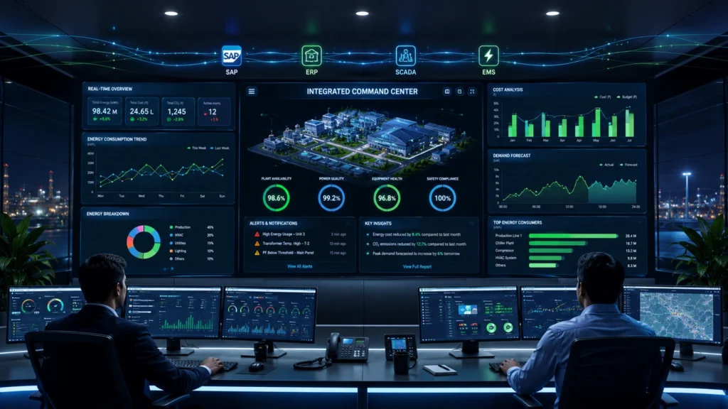
One View. Every System: How the Envolta Integrated Command Center Is Redefining Industrial Decision-Making Introduction: The Cost of Invisible Data Every plant manager has experienced it — standing in a Monday morning meeting, sifting through stale spreadsheets, waiting for numbers that arrived too late and in too many formats to mean anything useful. The information existed somewhere inside the plant. But the visibility? That was missing entirely. This is precisely the gap that Envolta Systems has engineered a solution for. The Envolta Integrated Command Center (ICC) is not simply another dashboard tool. It is a strategic intelligence platform built for the executives and operations leaders who need to move from firefighting to forward-looking — and who can no longer afford to govern a modern plant on yesterday’s data. What the Envolta Integrated Command Center Does At its core, the ICC aggregates data from every major operational system within an industrial facility into one unified, real-time view. The platform draws from SAP, ERP systems, HR platforms, SCADA networks, Energy Management Systems (EMS), and even manual logs — normalizing these disparate data streams into a single coherent truth. The tag line “One View. Every System. Endless Possibilities.” is not marketing hyperbole. When a CFO can see energy consumption trends, production output, HR-linked operational capacity, and maintenance alerts simultaneously — on a single display wall — the quality and speed of strategic decisions changes fundamentally. The Real Challenge: Why Plant Data Fails Decision-Makers Four Systemic Problems Envolta Solves Data ages quickly: By the time reports are compiled, the operational window for action has often closed. Numbers arrive after the moment: Reactive decisions based on delayed data are inherently less effective than proactive ones. Each system holds part of the truth: SAP knows procurement costs; SCADA knows machine runtime; EMS knows energy consumption — but no single system sees the complete picture. Knowledge lives in people, not systems: When a shift supervisor retires or moves teams, institutional knowledge disappears — a risk no modern plant can afford. The ICC dismantles all four of these barriers by acting as a real-time integration and normalization layer across every source of operational data. From Firefighting to Forward-Looking: The Operational Shift One of the most compelling promises of the Integrated Command Center is the elimination of the “morning data drill” — that frantic scramble to aggregate numbers before a leadership meeting. With the ICC, data is live, always accessible, and always current. Consider the specific outcomes Envolta highlights for its target users — CxOs, CFOs, Unit Heads, and Operations Heads. Instead of waiting for month-end surprises that reveal inefficiencies in hindsight, leaders can identify and correct deviations in real time. Instead of being led by reports, they can lead the room with data-driven confidence. Key Operational Benefits Automate data collection across all connected systems, eliminating manual entry errors. Eliminate data silos that fragment operational intelligence across departments. Reduce manual effort significantly, freeing teams to focus on value-generating activities. Enable decisions based on dynamic data, not static historical snapshots. Design and Visual Architecture: Built for the C-Suite The visual design of the Integrated Command Center is deliberately crafted for authority and clarity. The marketing visual depicts a professional command room — a wide-format multi-screen display wall populated with maps, trend lines, gauges, and dashboards, with a focused team of analysts working in front of it. The color palette of deep blue and luminous white communicates precision and technological confidence. This is not incidental. The aesthetics of a command center communicate organizational seriousness. When a plant’s leadership team operates from a purpose-built ICC, it signals to every stakeholder — investors, regulators, plant staff — that decisions here are made with rigour, not guesswork. Key Highlights Unified integration of SAP, ERP, HR, SCADA, EMS, and Manual Logs into one platform. Real-time visibility enabling dynamic, responsive decision-making for senior leadership. Elimination of data silos and morning data preparation routines. Designed specifically for CxO, CFO, Unit Head, and Operations Head use cases. Supports transition from reactive firefighting to proactive, forward-looking management. Promotes sustainable growth through smarter operational intelligence. Expert Insights: Why Unified Operational Intelligence Is the Future From a strategic management perspective, the convergence of operational technology (OT) and information technology (IT) data is one of the most transformative trends in industrial manufacturing. Traditionally, these two worlds — the shop floor and the boardroom — operated with entirely different data systems and cadences. The Envolta ICC represents a mature implementation of this convergence. By normalizing data from SCADA (an OT system) alongside SAP (an IT system), it creates what industry analysts often call a “single source of truth” — a concept that Fortune 500 companies have pursued for decades and that is now becoming accessible to mid-market and large industrial operators in India and beyond. From a marketing and branding standpoint, the product positioning is also astute. Targeting CxOs and CFOs rather than just IT or engineering teams reflects an understanding that technology adoption decisions in large plants are ultimately made — or blocked — at the leadership level. When the end user and the economic buyer are the same person, the sales cycle compresses significantly. SEO Section: Trending Searches This Solution Answers Industrial leaders across India’s manufacturing sector are increasingly searching for terms such as: plant data integration platform, real-time operational dashboard for manufacturing, SCADA and SAP integration, energy management command center, and CxO decision support system. The Envolta ICC sits squarely at the intersection of all these queries. Related semantic keywords include: industrial IoT dashboard, operational intelligence platform, plant performance monitoring, energy and production data integration, manufacturing executive dashboard, and digital transformation for heavy industry. Conclusion: The Information Exists. It Is Time the Visibility Did Too. Envolta Systems has identified and addressed one of the most persistent pain points in industrial management: the gap between data existence and data accessibility. The Integrated Command Center does not create new data — it makes the data you already have visible, actionable, and timely. For CxOs navigating competitive pressures, CFOs managing energy costs,

